|
CArl
Code Arlequin / C++ implementation
|
|
CArl
Code Arlequin / C++ implementation
|
In this example, we use the programs libmesh_assemble_lin_homogeneous__min_x_clamped and libmesh_assemble_lin_homogeneous__max_x_traction to assembly the decoupled system models using libMesh. These executables are not a "core" part of the C++ implementation of CArl, being used here only to demonstrate how the coupled solver works.
Submiting scripts/PBS_FETI_test_assemble_ext_solver_traction_test_1k.pbs or executing scripts/LOCAL_FETI_test_assemble_ext_solver_traction_test_1k.sh will run the commands
mkdir -p examples/coupled_traction_test/FETI_solver/brick_traction_1k/system_matrices
mpirun -np 4 ./libmesh_assemble_lin_homogeneous__min_x_clamped -i examples/coupled_traction_test/FETI_solver/brick_traction_1k/assemble_brick_traction_A_1k.txt
mpirun -np 4 ./libmesh_assemble_lin_homogeneous__max_x_traction -i examples/coupled_traction_test/FETI_solver/brick_traction_1k/assemble_brick_traction_B_1k.txt
Both programs use similar input files, and use the same parser function.
File: examples/coupled_traction_test/FETI_solver/brick_traction_1k/assemble_brick_traction_A_1k.txt
### 'Macro' system assembly parameters
# - Path to the model mesh
Mesh examples/coupled_traction_test/meshes/test_brick_A_1k.msh

# - Path to the physical parameter file
PhysicalParameters examples/coupled_traction_test/meshes/test_brick_I_1_physical.dat

# - Path to the weight function mesh
MeshWeight examples/coupled_traction_test/meshes/test_brick_mask.msh

# - Path to the weight function parameters
WeightIndexes examples/coupled_traction_test/meshes/test_brick_mask_idx.dat

# - System type (will determinate  which weights will be used)
SystemType  Macro

# - Output files base name
OutputBase examples/coupled_traction_test/FETI_solver/brick_traction_1k/system_matrices/traction_model_A
File: examples/coupled_traction_test/FETI_solver/brick_traction_1k/assemble_brick_traction_B_1k.txt
### 'Micro' system assembly parameters
# - Path to the model mesh
Mesh examples/coupled_traction_test/meshes/test_brick_B_1k.msh

# - Path to the physical parameter file
PhysicalParameters examples/coupled_traction_test/meshes/test_brick_I_1_physical.dat

# - Path to the weight function mesh
MeshWeight examples/coupled_traction_test/meshes/test_brick_mask.msh

# - Path to the weight function parameters
WeightIndexes examples/coupled_traction_test/meshes/test_brick_mask_idx.dat

# - System type (will determinate  which weights will be used)
SystemType  Micro

# - Output files base name
OutputBase examples/coupled_traction_test/FETI_solver/brick_traction_1k/system_matrices/traction_model_B

# > Calculate and export the rigid body modes vectors?
ExportRBVectors
Input file parameters:
Mesh: model mesh.PhysicalParameters: file containing the physical parameters - in this case the Young and shear modulus in  .
.SystemType: parameter used to tell the assembler which weight functions must be used. Can be either Micro or Macro.MeshWeight: mesh defining the domains of the Arlequin weight parameters.WeightIndexes: file containing the indices of the domains of the Arlequin weight parameters.OutputBase: filename base of the output files (including folders).ExportRBVectors: if this flag is set, the assembler will build and export the rigid body modes vectors.The SystemType, MeshWeight and WeightIndexes parameters are used to control the weight parameter functions used by the Arlequin method, noted as  in refs. 1 and 2. These parameters are used to guarantee a proper partitioning of the energy over the coupling region - and also over any region where both models are present, but are not coupled. The weight parameters follow the equations below:

The MeshWeight and WeightIndexes are used to determinate the regions and the values of  , while
 SystemType determinates which one must be used (  for
for Macro, for Micro).
Each element of the MeshWeight has a physical index which determinates which kind of region it represents. When assembling the matrices and vectors, the assembly programs will
SystemType and WeightIndexes, choose the weight parameter value.The check step is essentially a position search inside the MeshWeight, and hence it is recommended to use the smallest number of elements possible.
Here's the MeshWeight used here:
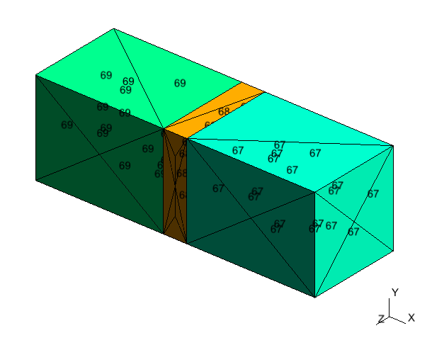
and here's the WeightIndexes file used in this example:
###
#     The file "test_brick_mask.msh" contains a "mask" that identifies, in the
#   full coupled model domain, the regions with:
#
#   - only one of the models
#   - the coupling area
#   - both models, but outside the coupling area
#
#     This file contains the physical indexes identifying each of these domains, and the
#   weights associated to them.
###

# Only the "macro" model
MacroDomainOnlyIdx 69

# Only the "micro" model
MicroDomainOnlyIdx 67

# Coupling area
CouplingDomainIdx 68

# Weight of the macro model at the coupling region
# [ micro weight ] = 1 - [ macro weight ]
AlphaCouplingMacro 0.5
Together, they will generate the weight parameter function below:
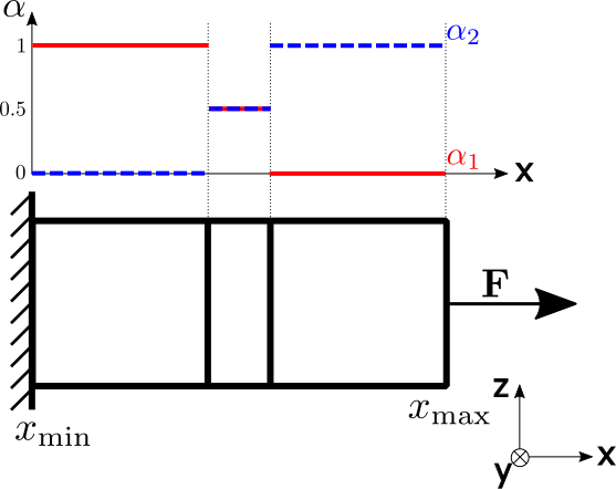
Two parameters were not used in this example: BothDomainsIdx and AlphaEps. They are used in cases where the domains overlap over a region, but are not coupled, with the former defining the MeshWeight's element physical index, and the latter the weight of the Macro model.
After running the external solver assembly programs, the following matrices and vectors will be created:
 traction_model_A_sys_mat.petscmat
 traction_model_B_sys_mat.petscmat
 traction_model_A_sys_rhs_vec.petscvec
 traction_model_B_sys_rhs_vec.petscvec
Micro / B model: traction_model_B_rb_vector_0_n_6.petscvec traction_model_B_rb_vector_1_n_6.petscvec traction_model_B_rb_vector_2_n_6.petscvec traction_model_B_rb_vector_3_n_6.petscvec traction_model_B_rb_vector_4_n_6.petscvec traction_model_B_rb_vector_5_n_6.petscvec
These matrices and vectors are saved using PETSc's binary format. The extensions .petsc*** is arbitrary. For each one of these files, an auxiliary file with an .info appended is created. It contains some information on how PETSc should read the matrix or vector.
1. T. M. Schlittler, R. Cottereau, Fully scalable implementation of a volume coupling scheme for the modeling of polycrystalline materials, Accepted for publication in Computational Mechanics (2017). DOI 10.1007/s00466-017-1445-9
2. D. Néron, H. Ben Dhia, R. Cottereau, A decoupled strategy to solve reduced-order multimodel problems in the PGD and Arlequin frameworks. Computational Mechanics pp. 1-13 (2016). DOI 10.1007/s00466-015-1236-0.
 1.8.10
